Description
A flex sensor is a resistive type sensor that changes its resistance based on the amount of bending or flexing applied.
When the flex sensor bends, the conductive elements within the sensor stretch or compress, causing changes in the resistance of the sensor.
The sensor is constructed using a flexible substrate like a thin strip of polymer or a printed circuit board, which contains conductive elements.
The resistance of the flex sensor typically increases as it bends or flexes, although there are some variations that exhibit the opposite behavior.
This sensor is widely used in robotics, prosthetics, wearable devices, gaming controllers, musical instruments, etc.
Flex sensors come in different lengths, shapes, and resistance ranges to suit various application requirements.
How Flex Sensors Work
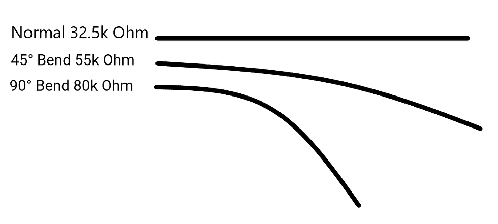
The conductive ink on the sensor acts as a resistive element. In its straight position, the sensor exhibits a resistance of approximately 32.5k ohms.
Bending the sensor causes the conductive layer to stretch, leading to a decrease in cross-sectional area and an increase in resistance.
At a 45° angle, this resistance is approximately 55K.
At a 90° angle, this resistance is approximately 80K.
When the sensor is straightened, the resistance reverts back to its initial value. By measuring the resistance, it is possible to determine the degree of bending of the sensor.
How to read Flex Sensor
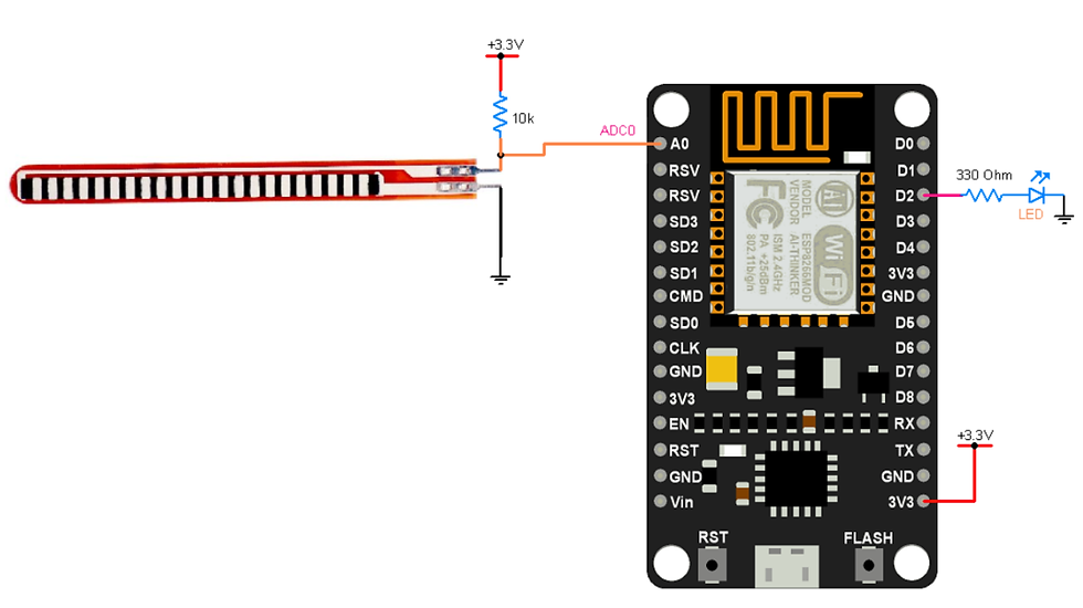
The flex sensor can be easily read by connecting it in a voltage divider configuration with a static resistor.
This arrangement creates a varying voltage output that can be measured using the analog-to-digital converter of a microcontroller.
Below is the simple voltage divider equation to measure the voltage across the flex resistor
For example, the esp32 works on 3.3V so with a 3.3V supply and a 10K resistor connected in series with a flex sensor.
When the sensor's position is straight, the resistance is around 32.5k then the output voltage is,
= 2.524V
When the sensor is fully bent (90°) the resistor increases to approximately 80K then, the output voltage is,
= 2.933V
Flex Sensor Interfacing with Nodemcu
Flex Sensor Code for Nodemcu
const int flexPin = A0;
const int ledPin = D2;

void setup() {
  Serial.begin(9600);
  pinMode(ledPin,OUTPUT);
}

void loop(){
  int flexValue;
  flexValue = analogRead(flexPin);
  Serial.print("sensor: ");
  Serial.println(flexValue);

  if(flexValue>3600)
     digitalWrite(ledPin,HIGH);
  else
    digitalWrite(ledPin,LOW);

  delay(20);
}
Output
Let’s Understand the code
Declares a constant integer variable flexPin and assigns it the value A0 pin
const int flexPin = A0;Declares a constant integer variable ledPin and assigns it to D2 Pin.
const int ledPin = D2;
In Setup Function,
Initialize the serial monitor
Serial.begin(9600);Set the ledPin as a OUTPUT
pinMode(ledPin,OUTPUT);
In loop Function,
Read the ADC values and store them on the flexValue variable
  int flexValue;
  flexValue = analogRead(flexPin);
  Serial.print("sensor: ");
  Serial.println(flexValue);
Now the flexValue reading goes above 3600 then torn on the LED
  if(flexValue>3600)
     digitalWrite(ledPin,HIGH);
  else
    digitalWrite(ledPin,LOW);

  delay(20);
} 


Comments