Description
The MAX7219 is a serially interfaced 8-digit LED display driver. It can be used to control up to 64 individual LEDs, or eight 7-segment displays.
The MAX7219 provides a convenient and cost-effective way to interface common anode 7-segment displays with microcontrollers or other digital logic circuits.
The module uses SPI communication for interfacing with the microcontroller.
These modules are compact and require few pins and wires compared to using singular 7-segment displays in cascade.
MAX7219 7-Segment Display Pin Configuration
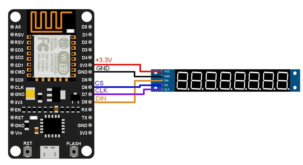
VCC: Connected to +3.3V
GND: Connected to the ground
DIN: This pin is used to input data into the MAX7219. Data is clocked into the MAX7219 on the rising edge of the serial clock signal.
CS: This pin is used to enable/disable the MAX7219. When it is LOW module is enabled and when the pin is HIGH the module is disabled.
CLK: This pin is used to provide the serial clock signal to the MAX7219.
MAX7219 7-Segment Display Hardware Connection with NodeMCU
Displaying the Digits using MAX7219 7-Segment Display
Here we have used the LedController library for displaying the numbers on the 7-Segment Display.
Download the library from the below link.
Simple Code to Display the Numbers on MAX7219 7-Segment Display
/**
 * @file LCDemo7Segment.ino
 * @author Noa Sakurajin (noasakurajin@web.de)
 * @brief using the ledcontroller with 7-segment displays
 * @version 0.1
 * @date 2020-12-30
 *
 * @copyright Copyright (c) 2020
 *
 */

#include "LedController.hpp"
/*
 You might need to change the following 3 Variables depending on your board.
 pin D8 is connected to the DataIn
 pin D7 is connected to the CLK
 pin D6 is connected to LOAD/ChipSelect
*/
#define DIN D8
#define CS D6
#define CLK D7

/*
 Now we need a LedController Variable to work with.
 We have only a single MAX72XX so the Dimensions are 1,1.
 */
LedController<1,1> lc;

/* we always wait a bit between updates of the display */
unsigned long delaytime=1000;

void setup() {
  //Here a new LedController object is created without hardware SPI.
 lc=LedController<1,1>(DIN,CLK,CS);
  lc.setIntensity(8); /* Set the brightness to a medium values */
  lc.clearMatrix(); /* and clear the display */
}

void loop() {
  for(int i=0; i<8; i++) {
    lc.setDigit(0,i,i,false);
    delay(delaytime);
  }
  lc.clearMatrix();
  delay(delaytime);
}
Now upload the code in NodeMCU.
The numbers from 0 to 7 will start displaying on the 7-Segment Display.
Output
Let’s Understand the Code
At the top, we have included the library LedController.cpp which includes functions and classes for controlling different types of LED displays, such as 7-segment displays, dot-matrix displays, or RGB LED strips.
#include "LedController.cpp"Next, we have defined the pins for NodeMCU such as,
#define DIN D8
#define CS D6
#define CLK D7
Then we created an object of the LedController class, which is instantiated with a template parameter of 1,1 to indicate that there is only one MAX7219 connected to the microcontroller.
LedController<1,1> lc;Now we will wait for a sec for the updates on the display
unsigned long delaytime=1000;
In the Setup Function, we have initialized the LedController object with the pin numbers specified by the DIN, CLK, and CS constants.
This creates a new LedController object without using hardware SPI.
And using the functions setIntensity and clearMatrix we can adjust the brightness of the display and clear the display respectively.
void setup() {
  //Here a new LedController object is created without hardware SPI.
  lc=LedController<1,1>(DIN,CLK,CS);
  lc.setIntensity(8); /* Set the brightness to a medium values */
  lc.clearMatrix(); /* and clear the display */
}
In the Loop Function, using the for loop we have repeatedly displayed the digits from 0 to 8 on the display.
For displaying we have used the setDigit function. After printing the digits, with the help of clearMatrix, we erased the digits and displayed them again.
void loop() {
  for(int i=0; i<8; i++) {
    lc.setDigit(0,i,i,false);
    delay(delaytime);
  }
  lc.clearMatrix();
  delay(delaytime);
}


Comments