
Overview of Nokia5110 Display


Nokia5110 is a graphical display that can display text, images, and various patterns.
It has a resolution of 48x84 and comes with a bac
It uses SPI communication to communicate with a microcontroller.
Data and commands can be sent through a microcontroller to the display to control the display output.
It has 8 pins.
For more information about the Nokia5110 display and how to use it, refer the topic Nokia5110 Graphical Display in the sensors and modules section.
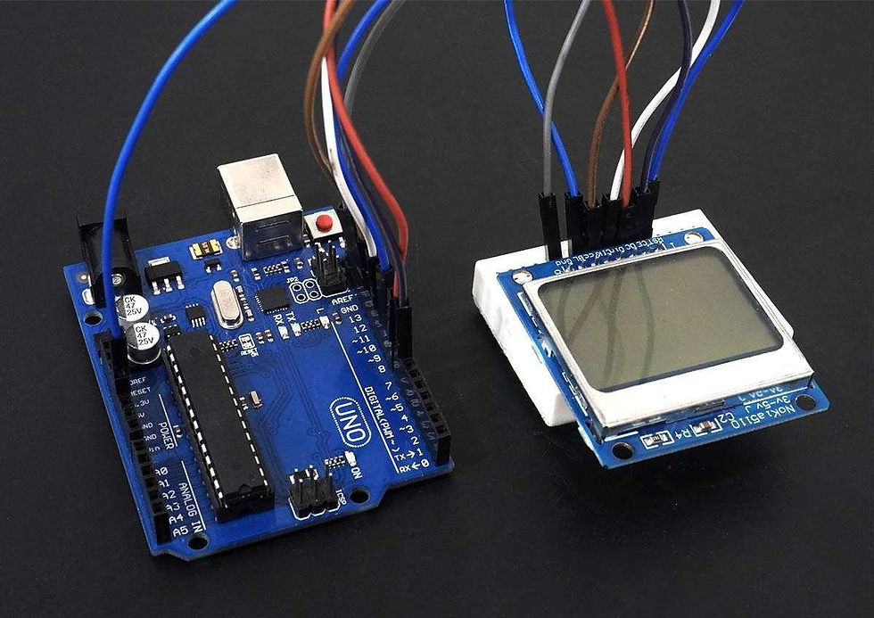
Connection Diagram of Nokia5110 Display with Arduino


Display Text, Patterns, and Images on the Nokia5110 Display Using Arduino Uno
Here, we will be using the Adafruit-PCD8544-Nokia-5110-LCD-library. This library is available on GitHub.
We will need the Adafruit GFX library as well for the patterns, images and text that we will be displaying on the display.
Extract these libraries and add them to the libraries folder path of Arduino IDE.
For information about how to add a custom library to the Arduino IDE and use examples from it, refer Adding Library To Arduino IDE in the Basics section.
The Adafruit Nokia library comes with an example sketch by Adafruit. You can directly upload that sketch to your device.
Here we have created an example sketch of our own, based on the functions defined in the two libraries.
Note: The drawBitmap function from the Adafruit_GFX library that is used for drawing images requires a peculiar array of the image.
For the Nokia5110 display, the array should contain image data scanned as 84 pixels per row and 48 such rows, starting from the origin of the image. Each element in the array (the array is a character array) contains information about 8 consecutive pixels. If we start at the origin, the first 11 elements (8 bits/pixels per element) in the array will contain the information about the 84 pixels in the 1st row (1 is a pixel on, 0 is pixel off). The next 11 elements will have information about the 84 pixels in the 2nd row and so on.
The 11th element will always carry 4 redundant bits since the display has only 84 pixels per row.
The data in the image array can be in hex form or binary form or decimal form.
Example: Consider that the first element in the image array is 0x0F (or 15 or 0B00001111)
In this case, the first 4 pixels in the first row will be off. The 5th, 6th, 7th and 8th pixels will be on.

Word of Caution: We need to use some application in order to get the image array from the image. There are many softwares available online that can be used for this purpose.
LCD Bitmap Converter is the software that we found useful and one that worked for us. It provides us the option to select how the image data can be scanned (vertical or horizontal), the endianness of the data (little endian or big endian). For the image data array to work with the drawBitmap function in the Adafruit GFX library, we need to use Horizontal Encoding and Big Endian (MSB to LSB) data format in the LCD Bitmap Converter software.
You can download LCD Bitmap Converter from this link: http://download.cnet.com/LCD-Bitmap-Converter/3000-2383_4-75984411.html
You can also download the LCD Bitmap Converter software setup from the Attachments section given below.
Refer this YouTube video link to know how to use the LCD Bitmap Converter software: https://www.youtube.com/watch?v=pDk4bZu6Lxg
Nokia5110 Display Code for Arduino Uno
#include <SPI.h>
#include <Adafruit_GFX.h>
#include <Adafruit_PCD8544.h>
#include "images.h"

// Software SPI (slower updates, more flexible pin options):
// pin 13 - Serial clock out (SCLK)
// pin 11 - Serial data out (DIN)
// pin 8 - Data/Command select (D/C)
// pin 7 - LCD chip select (CS)
// pin 9 - LCD reset (RST)
Adafruit_PCD8544 display = Adafruit_PCD8544(13, 11, 8, 7, 9);

void setup()   {
  display.begin();

  display.setContrast(50);  /* Initializes the display. Sets SPI freq, SPI data mode, Bit order */

  display.clearDisplay();  /* Clears the screen and buffer */

  display.setCursor(13,5);  /* Set x,y coordinates */
  display.setTextSize(1); /* Select font size of text. Increases with size of argument. */
  display.setTextColor(BLACK); /* Color of text*/
  display.println("Electronic"); /* Text to be displayed */
  display.setCursor(28,15);
  display.println("Wings");
  display.display();
  delay(500);
  /* Draw rectangle with round edges. Parameters (x_co-ord,y-co-ord,width,height,color) */
  display.drawRoundRect(5, 25, 25, 13, 1, BLACK);
  /* Draw circle. Parameters (x_co-ord of origin,y-co-ord of origin,radius,color) */
  display.drawCircle(45, 34, 10, BLACK);
  /* Draw triangle. Parameters (x0,y0,x1,y1,x2,y2,width,color). (x0,y0), (x1,y1) and (x2,y2) are the co-ord of vertices of the triangle  */
  display.drawTriangle(60, 38, 70, 25, 80, 38, BLACK);
  display.display();
  delay(1000);
  display.clearDisplay();
  /* Draw image. Parameters (x_co-ord, y_co-ord, name of array containing image, width of image in pixels, height in pixels, color) */
  display.drawBitmap(0, 0, Arduino_Logo, 84, 48, 1);
  display.display();
  delay(1000);
}

void loop() {
  display.clearDisplay();
  display.drawBitmap(0, 0, Smiley_1, 84, 48, 1);
  display.display();
  delay(300);
  display.clearDisplay();
  display.drawBitmap(0, 0, Smiley_2, 84, 48, 1);
  display.display();
  delay(300);
  display.clearDisplay();
  display.drawBitmap(0, 0, Smiley_3, 84, 48, 1);
  display.display();
  delay(300);
  display.clearDisplay();
  display.drawBitmap(0, 0, Smiley_4, 84, 48, 1);
  display.display();
  delay(300);
}
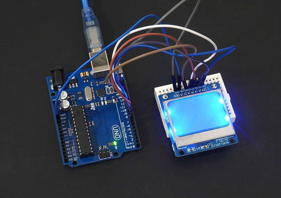
Output of Nokia5110 Display using Arduino Uno

תגובות